. Radiographie élémentaire et dentaire . Fig. 59. Figure 60. Fig. 59. Support de tube à rayons X simple.IIG. (E/S Tube avec blindage de protection en verre de plomb et diaphragme de compression. Lamer l'extrémité d'une bobine hii^h-frecjuoncy X-ra- lnl)e ma- l)o connoctctl avec le ruban de borne d'une bobine à haute fréquence. Wliile c'est théorique vrai, il se trouve parfois dans la pratique que les travaux de tube ont été trahis d'une manière que l'autre. Lorsque le tube est attelé, le courant oscille à travers lui et deux flux cathodiques sont générés. Un des flux est focasedcontre la cible et les rayons X sont donnés o
1001 x 2498 px | 8,5 x 21,1 cm | 3,3 x 8,3 inches | 300dpi
Informations supplémentaires:
Cette image peut avoir des imperfections car il s’agit d’une image historique ou de reportage.
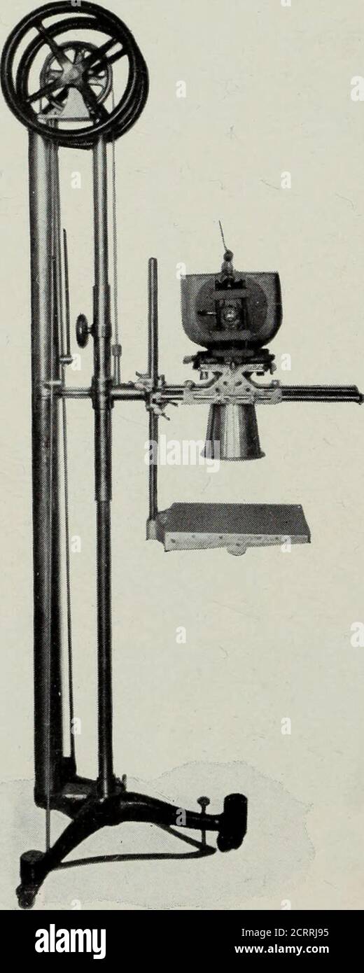
. Elementary and dental radiography . Fig- 59. Fig. 60. Fig. 59. Plain X-ray tube stand.Iig. (iO. Tube staiul. with a lead glass protection shield and a compression diaphragm. lather end of a hii^h-frecjuoncy X-ra- lnl)e ma- l)o connoctctl witheither terminal tape of a high-freciiiency coil. Wliile this is theoreticallytrue, it will sometimes be found in practice that the tube works betterhitched up one way than the other. When the tube is hitched up the current oscillates through it andtwo cathode streams are generated. One of the streams is focussedagainst the target and X-rays are given oft from the focal point, while 6o ELEMENTARY RADIOGRAPHY the other is focused into a funnel in the back of the target. (Fig. 56.)X-rays cannot be given off from this funnel; hence the tube lights up inthe active hemisphere as illustrated in Fig. 47. This funnel scheme is. Fig. 61. A pedestal, with a lead glass protection shield, compression diaphragm and plate holder. one way of taking care of one cathode stream w^hile the other is beingused for X-ray production. Another scheme is to move one cathode backso far that the cathode stream focuses before reaching the back of thetarget. (Fig. 57.) The high-frequency tube may be used to advantage on an inductioncoil which is generating a great deal of inverse current. One may wonder why a valve (Fig. 51) or a rectifier (Fig. 27)could not be used to cut out the flow of current in one direction, and atube like the one in Fig. 44, for example, used on a high-frequencycoil. Neither the valve nor the rectifier is capable of cutting out one X-RAY TUBES AND THE X-RAYS 6i direction of flow of a current of such high potential (voltage). Thevalve is able to cut out the inverse current of an induction coil becauseit (the inverse current) is comparatively weak; and the rectifier can cutout one wave of the commercial A.C.