. QST . par un ()U8 triode-pentodefrequency-controlled multivil)rator réglé pour fournir des fréquences de marqueur à des intervalles de 50 kc.la sortie est ample pour les récepteurs de type communication jusqu'à 30 Mc. * 22 Temple Street, Belmont 78, Mass. Capacité maximale de C4 à environ 60 ixfii.la sortie de la plaque du 6AK5 est alimentée à la grille de la section triode du multivibrateur 6U8.le diviseur de fréquence est constitué d'un multivibrateur à couplage électronique. En fonctionnement libre (c'est-à-dire non contrôlé par l'oscillateur à quartz), sa plage de fréquence^ s'étend d'environ 30 à 80 kc, selon le réglage de la fréquence
1497 x 1670 px | 25,3 x 28,3 cm | 10 x 11,1 inches | 150dpi
Informations supplémentaires:
Cette image peut avoir des imperfections car il s’agit d’une image historique ou de reportage.
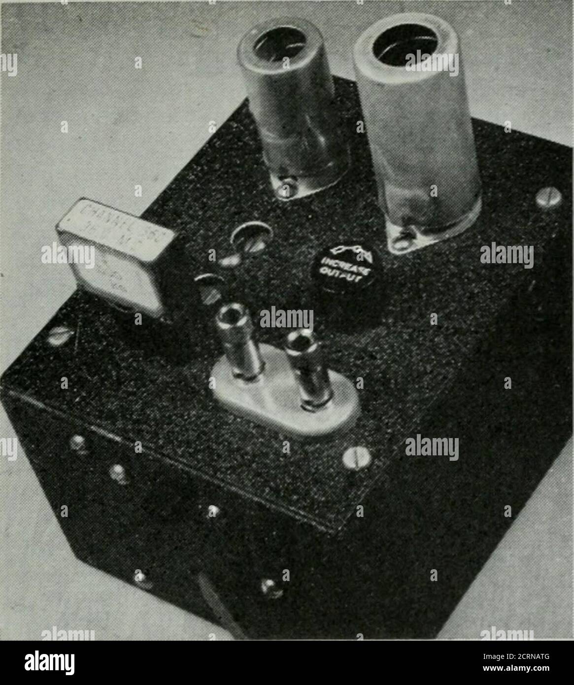
. QST . by a ()U8 triode-pentodefrequency-controlled multivil)rator adjusted toprovide marker frequencies at intervals of 50 kc.Output is ample for communication-type receiv-ers up to 30 Mc. * 22 Temple Street, Belmont 78, Mass. maximum capacitance of C4 to about 60 ixfii.Output from the plate of the 6AK5 is fed to thegrid of the triode section of the 6U8 multivibrator.The frequency divider consists of an electron-coupled multivibrator. When free running (i.e., not controlled by the crystal oscillator) its fre-quency^ range extends from about 30 to 80 kc, depending upon the setting of the frequency-adjusting resistor, R(, . When the multivibrator isfrequency controlled to operate at 51) kc, R(, has avalue of about 23, 000 ohms. Aside from the fea-ture of electron coujiling, which virtually elim-inates effect of load on operation of the fre-quency marker, the only unusual feature of themultivibrator circuit is the use of series resistorsin the grid circuits. These tin; not necessary but 14 QST for. This unit generates fretiuency marker signals at 50-kc.intervals, using surplus crystals in the 400- to 500-kc.region as the primary frequency source. In this frontview the oscillator tube is at the left rear and the multi-vibrator tube at the right. are used as an aid in producing a reasonably goodsquare-wave output at 50 kc. Adjustment The oscillator goes into oscillation easily whenthe crystal is plugged into its holder. The multi-vibrator is, perhaps, easiest adjusted by couplingits output to a communications-tjpe receiverand varying the resistance of Rr, untilmarker frequencies are produced at in-tervals of 50 kc. This adjustment ismost easily done in the broadcast band, or a similar low-frequency band of amultiband receiver. Proper adjustmentis that for which the note in the receiveris sharp and clean. It will probably befound that the desired condition ofoperation can be obtained with Rf, ad-justable throughout a small range ofangular rotation. If adjustment is madeb} me